

“In the world of F1, wheels are more than just components; they are the champions’ allies” formula 1 wheels explained.
Formula 1 wheels explained
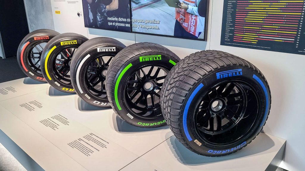
The FIA, which governs Formula 1 races, has implemented major modifications to the wheels used in F1 to enhance the warm-up phase and prevent overheating. Starting in 2022, 18-inch rims became mandatory, with tire diameters increasing from 660 mm to 720 mm. Nevertheless, the tire tread dimensions stayed the same, with the front measuring 305 mm and the rear 405 mm. Tire pressure and EOS camber limits are now adjusted based on various circuit conditions. Intermediate tires are 50 mm wider, while full wet tires are 100 mm wider in tread compared to dry ones. Pirelli, supplying tires since 2011, will continue its role until 2027, providing six different compounds from C0 (the hardest) to C5 (the softest).
formula 1 wheels
During a traditional Grand Prix session, each driver receives 13 sets of tires from Pirelli (8 soft, 3 medium, and 2 hard tires). After each practice session, drivers must return 2 sets of tires to Pirelli, leaving them with 7 sets for qualifying and the final race. Drivers must reserve 1 set of hard tires for the final race and 1 set of soft tires for Q3. In a Sprint Weekend, each driver gets 12 sets of tires (6 soft, 4 medium, and 2 hard tires). During qualifying sessions, drivers can only use soft tires, while in the sprint qualifying session, drivers must use medium tires for SQ1 and SQ2, and soft tires for SQ3. These rules apply in dry weather conditions.
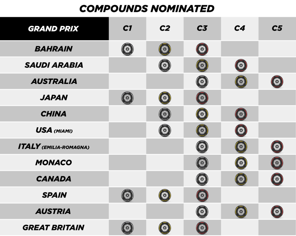
In 2024 Pirelli nominated compounds list for F1 tires for different circuits.
Soft Tires
Soft tires provide better performance but are less durable. They also provide maximum grip and
quick degradation. These tires are marked with a red circle. Pirelli uses C3, C4, or C5
compound to manufacture soft tires considering circuit conditions. Pirelli provides 8 sets of soft
tires in each Grand Prix weekend to each driver
Medium Tires
Medium hard tires are more durable than soft tires but less durable as compared to hard tires.
They provide much better performance than hard tires but less than soft tires. These tires are
specially designed for balanced speed and durability and are manufactured with C2, C3, or C4
compounds. These are indicated by a yellow circle. Pirelli provides 3 sets of medium tires in
each Grand Prix weekend to each driver.
Hard Tires
Hard tires are most durable in F1 races but provide the least performance. They are marked by
a white circle. These tires are made using C1, C2, or C3 compounds and are specially designed
for endurance, stability, and less grip. Pirelli provides 2 sets of hard tires to a driver in a Grand
Prix.
Intermediate Tires
Intermediate tires are used for versatile wet-condition performance in F1 races. These tires are
used when the circuit becomes wet or a little standing water is found. They can also be used in
dry circuits and are wider than dry tires. These tires are indicated by a green circle. Intermediate
tires can displace around 30 liters of water per second. They can provide better performance
than full-wet tires. Pirelli gives 4 sets of intermediate tires to a driver in each Grand Prix.
Full Wet Tires
Wet tires are used for heavy rain or a lot of standing water. These tires are wider compared with
dry or intermediate tires. They provide extreme grip also in heavy rainy conditions and are
capable of depressing impressive quantities of water. These tires are marked with a blue circle.
Full wet tires can displace around 60 liters of water. 3 sets of full wet tires are provided in every
Grand Prix session.
Drivers can’t share tires among themselves. This is strictly prohibited and even a driver can’t
help his teammate driver by giving him tires. Pirelli provides tires to each driver and he must
return used tires to them.

centrifuge balancing
Centrifuge balancing is a critical aspect of industrial operations, particularly in sectors like chemical, food, oil and gas, and pharmaceuticals. The purpose of this process is to ensure that centrifuges operate smoothly and efficiently at high speeds, thus preventing a range of detrimental issues that can arise from imbalance.
When centrifuges are unbalanced, the consequences can be severe. One of the most immediate repercussions is a reduction in product quality and an increase in waste. For example, in the food industry, an unstable centrifuge can lead to improper component separation, resulting in spoiled batches of products that are no longer fit for consumption. Moreover, imbalances can induce excessive wear on critical components such as bearings, shafts, and couplings. This wear not only diminishes the lifespan of the equipment but can also cause costly production downtimes.
Additionally, an unbalanced centrifuge generates excessive noise and vibration, which can create a hazardous work environment. Continuous exposure to such noise levels can affect worker comfort and health. The risks do not stop there; uneven loading on the centrifuge may lead to structural issues, such as cracks in the casing or loosening of fasteners, ultimately resulting in costly repairs or replacements.
Given these factors, dynamic centrifuge balancing becomes essential to maintaining operational integrity. The importance of balancing is amplified at higher rotation speeds, where the consequences of imbalance escalate rapidly. Regular inspections and preventive measures not only prolong the equipment’s lifespan but also avoid expensive breakdowns.
Dynamic balancing can be performed directly at the site of installation, utilizing the centrifuge’s own support bearings without the need for disassembly. This method has multiple advantages. First and foremost, it allows for quicker implementation, as there is no need to transport the centrifuge or dismantle its parts. A swift balancing procedure can significantly reduce production downtime. Furthermore, balancing occurs in the operational bearings, which eliminates distortions that could emerge if balancing was executed on a disconnected component. This minimizes minor operational issues that could disrupt routine functioning.
Another noteworthy benefit of on-site balancing is its minimal interference with the operational workflow. There is no need for complex assembly and disassembly tasks, which saves both time and resources for the facility. As a result, manufacturers can achieve optimal balancing outcomes, ensuring their equipment operates smoothly.
The Balanset-1A vibration analyzer is an instrumental device in the balancing process, providing accurate assessments of vibration levels and the execution of the balancing tasks. Noted for its precision and user-friendliness, the Balanset-1A is a versatile tool that enhances the dynamic balancing process significantly.
To effectively employ this device for balancing centrifuge rotors, proper preparation and meticulous setup are vital. The initial steps require the installation of vibration sensors at designated points; one should be placed on the centrifuge rotor’s front side while the other goes on the rear side. A tachometer must be securely affixed to a magnetic stand to read the rotations, and reflective tape should be applied to the rotor pulley to facilitate accurate measurement. After connecting all sensors and the tachometer to the Balanset-1A device, operators must make sure that the corresponding program on the laptop acknowledges these connections and select the two-plane balancing mode.
The balancing operations proceed with initial measurements to evaluate the existing vibration levels. A recorded test weight is installed initially in the first measurement plane, followed by a second round of vibration measurements that must reflect a distinct change (at least 20%). The process continues by moving the test weight to the second measurement plane and repeating the measurement, which will guide operators on the adjustments required for effective balancing.
Once the necessary changes are indicated, corrective weights must be accurately installed and securely fastened. The final step involves running a conclusive vibration measurement that confirms whether the balancing was effective. If the program advises additional weight, further adjustments should be made to achieve a flawless balance.
Completing this balancing procedure calls for careful removal of sensors and devices used, along with the documentation of all relevant performance data in a comprehensive balancing report. The importance of adhering to established balancing standards, such as ISO 1940-1-2007, cannot be overstated. Such standards stipulate acceptable vibration levels for different equipment classes. Compliance ensures that the centrifuge remains efficient, dependable, and minimizes wear—critical factors particularly under high-stress operational conditions.
In conclusion, neglecting centrifuge balancing leads directly to higher wear rates and potential operational failures. Regular dynamic balancing with state-of-the-art equipment like the Balanset-1A is indispensable for ensuring safe and optimal machinery performance. It not only protects against costly repairs but also secures production uptime, contributing to a highly efficient industrial operation. Investing in reliable balancing tools and maintaining stringent adherence to balancing standards will ultimately yield significant returns through enhanced equipment reliability and operational productivity.
Watch YouTube Short
Enhancing Mining Equipment Balancing Techniques with Balanset-1A
In the mining industry, the efficiency and longevity of equipment are paramount. Vibration and imbalance in machinery can lead to significant downtimes and costly repairs. The Balanset-1A device by Vibromera offers a comprehensive solution to optimize mining equipment balancing techniques, ensuring smooth operations and reducing maintenance costs.
Why Balance Rotors?
Rotor balancing is crucial for the proper functioning of mining equipment. An unbalanced rotor can cause excessive vibration, leading to premature wear and failure of mechanical components. The Balanset-1A is designed to accurately identify and correct rotor imbalances in various machines, including crushers and centrifuges.
Preparation for Balancing
Before using the Balanset-1A, it’s essential to ensure that the equipment is in good working order. The rotor must be free of contaminants, and all components should be securely fastened. Any defects in the machine must be addressed before proceeding with the balancing process.
The first step involves setting up vibration and phase sensors according to guidelines, ensuring accurate measurements. It’s advisable to perform initial measurements in vibrometer mode to establish baseline vibration levels.
Initial Vibration Measurement
Begin by weighing the test weight and recording its mass and radius. Run the rotor to measure the initial vibration level, which helps in assessing the amplitude and phase of the existing imbalance. If the overall vibration level (V1s or V2s) significantly exceeds the rotational component (V1o or V2o), further inspection of bearings and mounts is recommended.
Balancing in Two Planes
The Balanset-1A allows for dynamic balancing in two planes. Start by placing the test weight in the first balancing plane and measure the change in vibration. A 20% change in amplitude or phase indicates partial correction of the imbalance. Repeat the process in the second plane to gather the necessary data for precise correction.
Correcting Imbalance
Using the data collected, the Balanset-1A software calculates the optimal weight and angle for corrective measures. Remove the test weight and install the suggested corrective weights at the specified angles. This step is crucial for achieving a significant reduction in vibration levels.
Final Checks and Completion
Once the corrective weights are in place, run the rotor again to verify the balance. If the vibration levels have reduced to acceptable standards, the balancing process is complete. Otherwise, the software will provide guidance for additional adjustments.
Advanced Features of Balanset-1A
The Balanset-1A is equipped with advanced features, such as a polar graph for visualizing imbalances, a tolerance calculator based on ISO 1940, and the ability to restore previous sessions. These features enhance the accuracy and efficiency of the balancing process, making it suitable for both single and serial production environments.
Conclusion
Incorporating the Balanset-1A into your mining equipment balancing techniques can significantly improve machinery performance and reliability. By addressing rotor imbalances effectively, this device helps minimize wear, reduce downtime, and extend the lifespan of critical equipment in the mining sector.
Contact Information:
For more information about our Balanset balancing devices and other products, please visit our website: https://vibromera.eu.
Subscribe to our YouTube channel, where you will find instructional videos and examples of completed work: https://www.youtube.com/@vibromera.
Stay updated with our latest news and promotions on Instagram, where we also showcase examples of our work: https://www.instagram.com/vibromera_ou/.
Buy Balanset-1A on Etsy
Balanset-1A OEM on Etsy